Cylinder Head Temperature (CHT) sensor — replacement
Warning: Wait until the engine has cooled completely before beginning this procedure.
Caution: The CHT sensor is not to be reused. Install only a NEW CHT sensor once it is removed.
Note: The CHT sensor is a major component of the Fail-Safe Cooling system. This sensor varies the value of its voltage output in accordance with temperature changes. The change in the resistance values will directly affect the voltage signal from the CHT sensor. As the sensor temperature decreases, the resistance values will increase (voltage increases). If the cylinder head temperature exceeds 265-degrees F, the PCM disables half of the fuel injectors at a time. The cylinders that do not receive fuel act as cooling air pumps for the other cylinders. If the temperature exceeds 330-degrees F, the PCM disables all of the fuel injectors. A problem in the CHT sensor circuit will set a diagnostic trouble code.
Four-cylinder models
1. Disconnect the cable from the negative battery terminal (see Engine electrical systems).
2. Remove the air filter outlet duct, then disconnect the charge air cooler inlet pipe (see Fuel and exhaust systems).
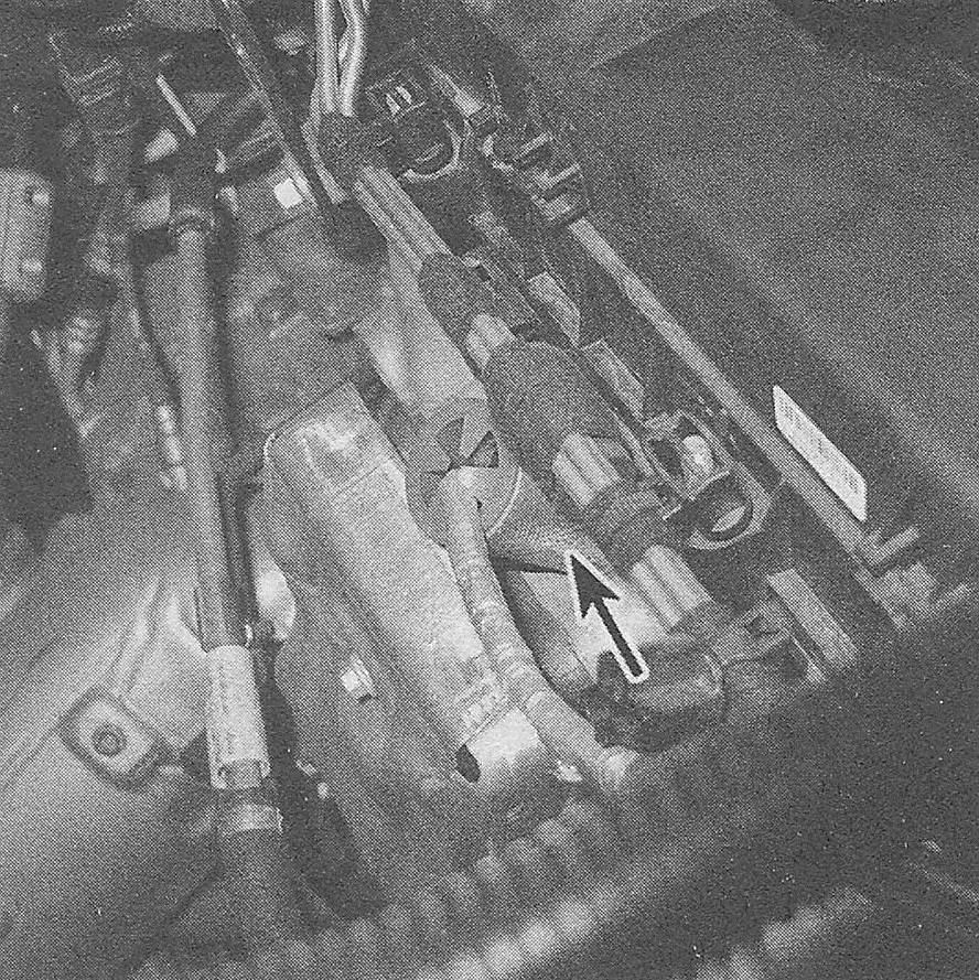
3. Pull back the rubber weather cover from the CHT sensor electrical connector and disconnect the connector (see illustration).
7.3 The CHT sensor is located on the back side of the cylinder head (four-cylinder engine)

4. Unscrew the CHT sensor from the cylinder head.
5. When installing the CHT sensor, tighten it to the torque listed in this Chapter’s Specifications. Installation is the reverse of removal.
V6 models 2.7L models
6. Remove the two fasteners on the engine cover. Lift up at the front and unhook the retainers at the rear of the cover to remove.
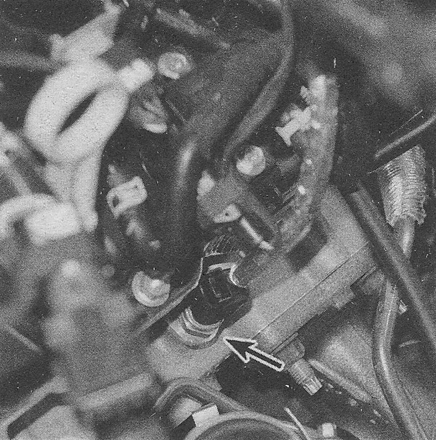
7. Locate the CHT sensor in the driver cylinder head and disconnect the electrical connector (see illustration).
7.7 The CHT sensor is located near the left -bank turbocharger (2.7L model shown

8. Unscrew the CHT sensor from the cylinder head and discard.
9. Installation is reverse of removal. Tighten the NEW CHT sensor to specification shown in this Chapter’s Specifications.
3.5L and 3.7L models
Note: The CHT sensor is screwed into the rear cylinder head below the lower intake manifold.
10. Disconnect the cable from the negative battery terminal (see Engine electrical systems).
11. Remove the lower intake manifold (see V6 engines).
12. Disconnect the CHT sensor electrical connector.
13. Unscrew and remove the CHT sensor.
14. When installing the CHT sensor, tighten it to the torque listed in this Chapter’s Specifications. Installation is otherwise the reverse of removal.